My first PCB
Programming the Board
Table of Contents
Introduction
With the board completely assembled there is now only one thing left: Programming some cool example code. Blinking one of the LEDs already worked as a first test in the previous blog post. Now we want to light up all of the LEDs at once with varying intensities. To make it interactive we also want to read out the buttons. As a note, all of the code can be found in the blossom-firmware repository.
Let's get started.
Controlling the LEDs
Charlieplexing
The LEDs on the Blossom board are connected in a smart way so that we can control all 12 of them with only 4 microcontroller pins. This technique is called Charlieplexing, the schematic looks like this:
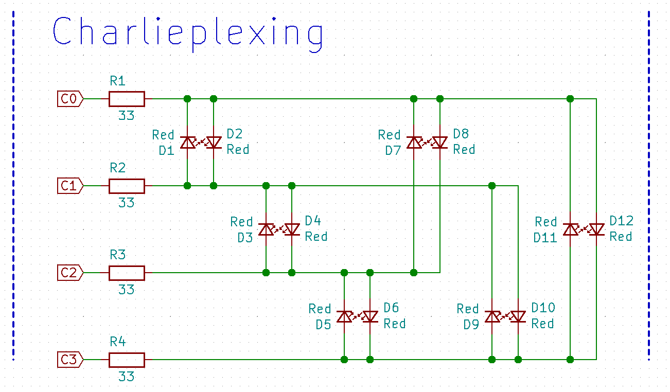
Now, we want to control the LEDs. For that we are going to write a function called activateLED (emphasis on the singular) to light up only one LED at once.
Let's say we want to control the LEDs D1 and D2. We must first set the two pins C0 and C1 to output and then set their low/high level respectively.
This is done as follows:
// D1-D2
DDRB |= ((1<<LED0) | (1<<LED1));
if (whichLED)
{
  PORTB |= (1<<LED0);
  PORTB &= ~(1<<LED1);
}
else
{
  PORTB |= (1<<LED1);
  PORTB &= ~(1<<LED0);
}
where whichLED controls which LED lights up.
Note that the other pins must be set as input to not interfere. This is done the easiest by first setting all pins as input and deactivating the pull-up:
PORTB = 0x00;
DDRB = 0x00;
To complete this function for all LEDs it looks like this:
void activateLED(uint8_t index)
{
  PORTB = 0x00;
  DDRB = 0x00;

  switch (index>>1)
  {
    case 0:
      // D1-D2
      DDRB |= ((1<<LED0) | (1<<LED1));
      if (index & 0x1 ) { PORTB |= (1<<LED0); PORTB &= ~(1<<LED1); }
      else { PORTB |= (1<<LED1); PORTB &= ~(1<<LED0); }
      break;
    case 1:
      // D3-D4
      DDRB |= ((1<<LED1) | (1<<LED2));
      if (index & 0x1 ) { PORTB |= (1<<LED1); PORTB &= ~(1<<LED2); }
      else { PORTB |= (1<<LED2); PORTB &= ~(1<<LED1); }
      break;
    case 2:
      // D5-D6
      DDRB |= ((1<<LED2) | (1<<LED3));
      if (index & 0x1 ) { PORTB |= (1<<LED2); PORTB &= ~(1<<LED3); }
      else { PORTB |= (1<<LED3); PORTB &= ~(1<<LED2); }
      break;
    case 3:
      // D7-D8
      DDRB |= ((1<<LED0) | (1<<LED2));
      if (index & 0x1 ) { PORTB |= (1<<LED0); PORTB &= ~(1<<LED2); }
      else { PORTB |= (1<<LED2); PORTB &= ~(1<<LED0); }
      break;
    case 4:
      // D9-D10
      DDRB |= ((1<<LED1) | (1<<LED3));
      if (index & 0x1 ) { PORTB |= (1<<LED1); PORTB &= ~(1<<LED3); }
      else { PORTB |= (1<<LED3); PORTB &= ~(1<<LED1); }
      break;
    case 5:
      // D11-D12
      DDRB |= ((1<<LED0) | (1<<LED3));
      if (index & 0x1 ) { PORTB |= (1<<LED0); PORTB &= ~(1<<LED3); }
      else { PORTB |= (1<<LED3); PORTB &= ~(1<<LED0); }
      break;
    default:
      PORTB = 0x00;
      break;
  }
}
(Yes, a lot of repetitive code)
Now we are able to control one LED at once and with some tricks (at least to our eye) all of them at once.
Controlling multiple LEDs
I refer here to the wikipedia article of Multiplexing for an in depth explanation. Basically, one LED is driven after another but in such a quick succession that it tricks our eyes into seeing a continuous picture. But we can not only simply turn the LEDs on or off in their time interval, but we ca vary the time it is active leading us to the next topic.
Varying Intensity
To vary the intensity we reserve a fixed time interval for every LED in which it can be either full on, fully off or anything in between:
Lets say the interval consists of 10 slots, where . means off in that slot and = means on:
This would be fully off:
[..........]
This fully on:
[==========]
And this would be half-lit:
[=====.....]
You get the idea. Now in the real implementation I used 48 slots for a smoother transition, but I had a problem: Small changes in the upper value range hardly change the intensity of the LEDs.
To fix this we need to scale our values more the higher the value is, basically a square function. I decided on this formula
(x/15)^2 * 48
which looks like this:
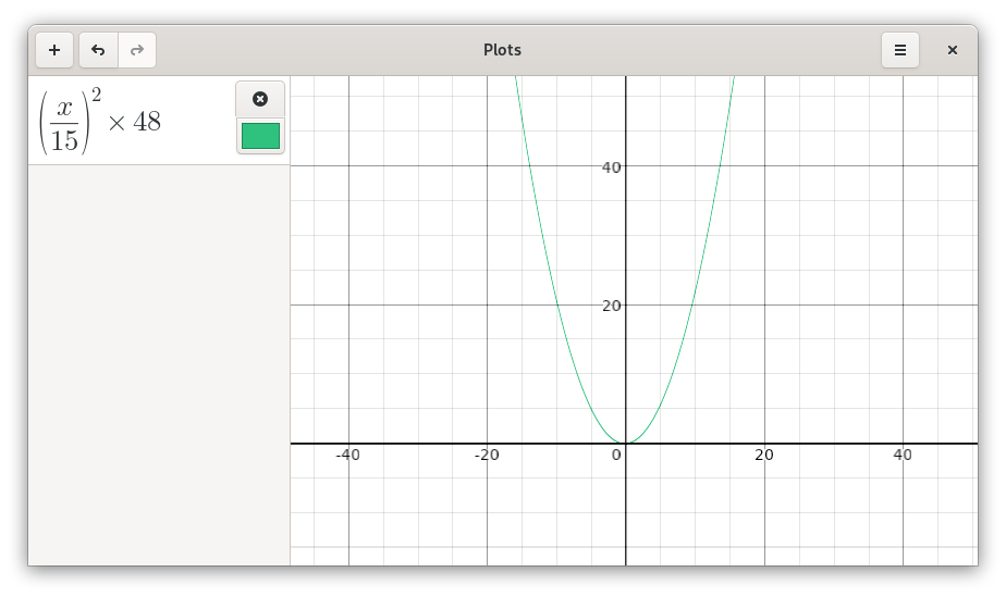
But this also reduces the number of different intensity levels we can have to 16, well you can't have everything.
Out of these values I created a look-up table called intensity_lut:
uint8_t intensity_lut[16] =
{
  0,
  1,
  2,
  3,
  4,
  5,
  8,
  10,
  14,
  17,
  21,
  26,
  31,
  36,
  42,
  48,
};
As you can see lower values change the on-duration only slightly, and higher values have a bigger impact on the duration resulting in visible changes in brightness.
With some animation this looks really good:
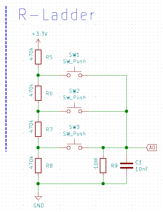
Reading the ADC to register button presses
To detect any button presses we need to measure the voltage of C1. Depending on which button is pressed C1 is at another voltage level.
For that we first need to initialize the ADC of the ATtiny:
void initADC()
{
  // Set Vcc as voltage reference
  // and left adjust the result
  // Set ADC2 (PB4) as input
  ADMUX = (1<<ADLAR) | (0b0010<<0);

  // Disable digital input for ADC2
  DIDR0 |= (1<<ADC2D);

  // Enable ADC and interrupt
  // Use 128 division factor
  ADCSRA = (1<<ADEN) | (1<<ADIE) | (0b111<<ADPS0);
}
Conversions are triggered continuously from inside a timer. The ISR looks like this:
ISR(ADC_vect)
{
  // Read the result (high byte)
  uint8_t result = ADCH;

  ...
}
We then compare the result to the voltage levels to determine which button was pressed. The values were calculated from the three possible voltage levels and seem to work just fine.
#define BUTTON_0_TRESH 160
#define BUTTON_1_TRESH 96
#define BUTTON_2_TRESH 32
To make access of the button states more convenient I have added a global structure which includes the current state and how long the button is pressed.
struct {
    button_state_t state;
    uint16_t time_ms;
} typedef button_t;

struct {
    button_t button_0;
    button_t button_1;
    button_t button_2;
} typedef buttons_t;
The buttons can have one of three possible states.
enum {
    NOT_PRESSED = 0,
    DEADTIME,
    PRESSED
} typedef button_state_t;
Wait, three? Aren't there only supposed to be two states: pressed and not pressed? Well, when we press button 0 with the highest voltage, we also traverse the voltage range of button 1 and 2. To prevent any misdetections I have added a small deadtime: Only after the voltage level stays in the voltage range for a certain time the button is actually pressed. This adds a small delay to pressing buttons, which in reality isn't noticeable.
#define DEAD_TIME 50 // ms
It just feels like pressing a "normal" button:
Conclusion
I think this should explain the core concepts well enough. If you want to have a look at the full code with various patterns and sequences have a look at the blossom-firmware repository.
See you in the next series!